Showing posts with label Modelling. Show all posts

Tuesday, 10 January 2017

AC Cobra Modelling Challenge Outcome

I'm really happy to conclude this little project I've had on the fly, a Car Modelling Challenge. The primary objective of the project was (as per the description) to focus on the modelling of a vehicle. I chose the AC Cobra 427 partly because it's iconic curved bodywork presented a challenge as it would clearly force me consider the changes in its geometry, the curves as pinch points: and partially because I've always been fascinated by the vehicle, even as a kid. I still had one of those 1:30 scaled toys of the Cobra on my window seal.
All in all it's been nice to develop my ability to model accurately, render, texture and composite.


AC Cobra 427 Outcome Cam 01


AC Cobra Outcome Camera 03


Monday, 5 December 2016

Vehicle Visualisation: PT1: Modelling

I'm delighted to share with you all the first update of my latest personal project; creating a vehicle visualization based from orthographic sketches. This first post covers a step by step of the modelling construction process of the vehicle and some little hints and tips for people who may find this a daunting task or are simply interested in how I tackle modelling procedures inside 3DS Max

Tip 01: It's really quite handy to arrange your view ports/ screen space in such a way which is comfortable  and coherent for the user. I personally quite like to use my second screen to cycle through reference images, which gives me a better idea of the shape and contours of my model WIP and an easy way to compare differences. 


Fig.1 Screen Layout 

My second tip is to utilize your modifier stack so that you can always move down onto the 'fundamental levels' (if you will) to edit the shape and curvature of the model at hand. Creating a mesh should be tackled in the same way as laying the foundations for a home. (If the foundations are incorrect you can guarantee the bricks which come later will not hold). My typical stack could contain a modifier selection something like this... 

Shell
Turbosmooth
Symmetry
UVW Map
Edit Poly

...theres no wrong or right way to model.But I would strongly encourage a modifier stack somewhat similar  to the above as you can quickly move up and down the stack, and vehicles are generally pretty symmetric (so you're cutting your work flow in half by moving back and forth between the symmetry modifier). 

My third tip is to use the see-through and clay modes to help visualize your model WIP. This tip is more a personal choice. See-through mode (Fig.2) can be accessed by RMB and clicking on the object properties tab, allows you to model your mesh and display a reference/orthographic scale drawing to model against. Obviously very handy. 
Secondly I like to use clay modelling a lot because I find that various textures and colours inside the viewport can become distracting and hinder the objective of working out the shape of the model. 3DS Max will by default assign different colours to different layers, so if you're solely focusing on modelling and not texturing at the same time, it's pretty easy to end up with a multi coloured viewport.


Fig.2 Car Elements in Progress


Fig.3 Clay Mode Modelling 

My fourth and final quick tip for modelling is... do not be afraid to model separate elements inside separate scenes before merging them into a master file. This was particularly helpful for challenging geometry like the wheels, which I just find easier to start from scratch in a separate file to edit it in.


Fig.4 Wheel WIP.

Without further ado, here are some very quick renders for my work in progress. I hope these quick tips help some of you out there, even though I can appreciate a lot of this is basic or common knowledge. Thanks!


Fig.5 Wheel Mesh

Fig.6: Wheel Mesh Wireframe 


Fig.7: AC Cobra Front Cam

Fig.8: AC Cobra Rear Cam
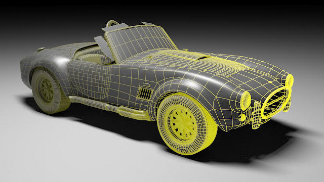

Fig.9: AC Cobra Front Cam Wireframe

Fig.10: AC Cobra Rear Cam Wireframe


Fig.11: Beauty Shot


Sunday, 3 July 2016

Product Visualisation: Rendering a Wedding Band

In this post I'm just going to take you through a few advanced modelling techniques I used to create this wedding ring/band, and again highlight some of the processes I used to generate a render for this product visualisation. 


Fig.1 The Final Render.

Before rushing into modelling it's good to look at reference images to work out how you can minimise your workflow and start to think about what techniques you will deploy throughout the creation of the object to ensure you are working in an optimal workflow. 


Fig.2 Creating a Repeating Segment.

One of the first features I noticed in rings/wedding bands were repeating sections. An easy way to minmise and enhance control over your workflow is to build repeating sections of the band and then deform them into the specific shapes. 
In my case I used the a square socket shape for the diamond sections of the rings to create a repeating shape from.
This involved me creating reference objects and then deforming them along a spline path using the 'Path Deform' modifier. Reference objects allowed me to control the entirety of the diamond repeat sections by modifier just one portion. I.e you can then apply UV mapping or any modifier to the original to effect the references.


Fig.3 Setting up splines as deformation pathways for repeating references.

The next step of the process was creating a diamond that actually looked realistic. To do this I had to look at how jewelers cut diamonds in reality and then attempt to make a similar geometric structure. Ironically I found this easiest to start with a six sided cube and then to use the 'Cut' modelling tool in the appropriate places.

Fig.4 Sculpting the Geometry of the Diamond (Side).


Fig.5 Sculpting the Geometry of the Diamond (Top).

In order to create a sharp edge on the diamond geometry I simply used the auto smooth function at a degree of 1 over the entire object in the edit poly modifier settings. See Fig.6


Fig.6 Creating Hard edges on the Diamond. 

As described above the next step was then to add the diamond to the repeating socket section, simply by attaching it via an edit poly on the original repeating socket section and then to UV the original, diamond and socket together. The result was that every section was updated simultaneously across each specified curve of the ring.


Fig.7 Repeating Diamond socket with UVs 


Here are the results before the final texturing and lighting... 


Fig.8 Ring GreyScale

Fig.9 Rings UVs

Thursday, 19 May 2016

Automotive Design: PT 1. Modelling.

In my latest project I've decided to model a car from scratch, inside 3DS Max. 
In the initial stages I studied a lot of reference images of cars to make sure I got my design right. To create a realistic sports car design the car needed to follow certain patterns and an overall design language so all elements could exist cohesively. (If the rear looked a completely different design from the front of the car I would fail to create a sense of realism in the model). 
The two images below show my drawing designs I used as image planes inside of Max. Normally I would tidy these images up, make sure all edges are perfectly aligned and use a block black brush to make the lines stand out; but since this was my personal project and I was still undecided on certain parts of the car, I used this these images as a mere guide to figure it out in Max. 

Fig.1 Aerial Orthographic 


Fig.2 Front Orhtographic

The next step was to start blocking in the shapes and model the car. I started with the side panels and worked outwards. I also made the tyres inside a separate file and imported them in. This helped to keep the viewport clean. 
The general rule of thumb here is to create utilise a non destructive workflow, using an edit poly modifier for your Low Res, a turbosmooth to round the mesh and a symmetry modifier down the middle to speed the process. (A lot like a the modelling process for a character). 


Fig.3 Car Model Mirrored


Fig.4 Car Model (Half)


Fig.5 Car Model Rear

To finish up modelling I posed the car, with a light set up and cameras, ready for the texturing and rendering processes to follow... By rendering I was also able to pick out certain parts of geometry and improve my mesh, by adding division lines in the panelling for example or sharpening edges so I could meet that design language I had spent a long time thinking about at the drawing stage. 


Fig.6 Camera/ Light SetUp


Fig.7 Modelling Improvements


Monday, 29 February 2016

Interior Vis: Modelling

I keep on pushing myself with a variety of personal projects. In my second interior visualization in 3DS Max I'm coming towards the end of the modelling process. This involves modelling assets to populate the scene (consequently to make it look more interesting).  See below are a series of pictures of just some of the assets I've been modelling lately. In some of these assets such as the sofa I used Marvelous Designer to simulate realistic folds and bends in the fabrics which you simply couldn't achieve inside Max. 


Fig.1: A sofa asset featuring cushions simulated from Marvelous Designer.


Fig.2: A Lamp. Creating a VRay blend material of a lightmtl and a glassy plastic was key in producing this lit effect. 


Fig.4 The Room Step One


Fig.5: The Room Step two 


Fig.6


Fig.7


Fig.8

Thursday, 11 February 2016

Interior Visualisations 02: Start Point

As a small side project I've assigned myself the task of creating another interior visualisation. This time we will be working with a swanky bedroom concept and I will be using VRay rather than Mental Ray to render and light the images. 

This post highlights that starting process for the 3DS Max scene, as you can see I've started to block in some basic shapes for the room. What you can't see is that I've carefully created layers for the walls, ceilings, lights and furnishings so that I can move through the scene as efficiently as possible. It pays to keep your scene tidy and maneuverable, especially when you have to hand it over to a colleague or artist. 

Secondly I've also worked with Marvelous Designer in this post to create some awesome bed sheets and pillows. This is a very easy to use program which involved exporting the bed frame to simulate and stitch a cloth over. The major advantage of MD is that it is easy to control the volume of the cloth (via elasticity and compression settings), as well as easily sewing parts of cloth together and making realistic cuts/welds and seams into the cloth.


Fig.1: Snap shot of the VRay Render in progress


Fig.2: Welding seams in Marvelous Designer


Fig.3: Importing the Cloth as an OBJ to Max


Fig.4: Creating volume inside a duvet by adding seams


Fig.5 Extra added elements to create a realistic feel to the bed


Fig.6: The starting point for the visualisation. 


Friday, 11 December 2015

Bourbon_Modelling Complete

It's been a while since I last posted, understandably the Christmas period is extremely busy with work. However bit by bit I've finally, finally managed to get Bourbon modelled!
I'm very happy with the progress, this is my first attempt at modelling a character inside Max and I managed it all without the aid of a single tutorial.
I'll be making a bunny gun for the little soldier too, (which shoots carrots, of course) but the next step is going to be looking into UV'ing and rigging him which as far as I can see looks completely different from what I'm used to in Maya. Game on!


Fig.1 Bourbon Mesh Front

Fig.2 Bourbon Mesh Rear


Thursday, 26 November 2015

Bourbon_Modelling

Just a quick update of my WIP so far. Bourbon is well under way, I'll just have to model all the extra little details now! On a side note I'm really liking the EdgeTex wireframe shader map in VRay.


Fig.1


Fig.2


Fig.3


Fig.4


Fig.5


Monday, 9 November 2015

GOW LAV_Concept Modelling Progress!

I'm very pleased to say that my LAV concept for the HCR Hardcore Modelling Challenge has reached its conclusion for the modelling process. (I'll remind you that the objective of this competition was to work towards a high quality render in minimal time, starting from scratch and moving to a complete outcome under the pressure of a time constraint). Sadly this means that although on the vast part my modelling has been relatively quick I cannot finesse details as I'll have to move onto the next process at hand to get this render out on time; UV Layout.
Here is a grey scale render of the LAV Concept, the VRay displacement doing wonders to the ground plane, and I'll look forward to posting the progress soon.


Fig.1 Modelling process complete (GreyScale)